Low voltage cable failures are often not caused by the cable itself — they happen at the connection points. An NRC analysis of 1,035 low voltage cable failures found that hookup and panel wire failures accounted for 36.4% of all failures, and connector failures accounted for 30.3% — together over 66%. A DNV GL survey of approximately 170 underground cable failures found that 69% of faults originated in cable accessories (joints and terminations), not the cable body.
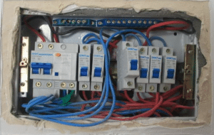
These numbers point to three areas that procurement often overlooks: terminal connections, overload margins, and installation protection.
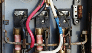
Improper torque. NEC 2017 added Section 110.14(D), requiring that where a tightening torque is indicated as a numeric value on equipment or in installation instructions, a calibrated torque tool shall be used to achieve the indicated torque value. NEC 2020 further revised this to “approved means,” including torque tools, shear bolts, or breakaway devices with visual indication. Loose connections caused by improper torque increase contact resistance over time, causing terminal temperature rise, eventually leading to insulation degradation, arcing, and fire.
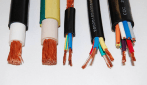
Wrong conductor class. This is the most overlooked issue in procurement. If Class 1 solid or Class 2 stranded conductors are used in control cabinets or panel wiring, repeated bending during installation and maintenance causes work-hardening — the copper becomes progressively more brittle until it fractures at the termination. The break is not visible during visual inspection. The fault presents as intermittent high-resistance contact, unexpected tripping, or terminal overheating. Class 5 fine-stranded conductors distribute bending stress across many individual strands, each undergoing elastic bending without accumulating enough plastic deformation to break.
Oxidation and corrosion. In the NRC analysis of 335 connector failures, oxidation/corrosion/dirt was the most significant failure cause, at 44%. Both aluminium and copper form oxide layers when exposed to air. Oxidation at improperly torqued connections increases resistance and further accelerates temperature rise.
The heat generated in a cable is proportional to the square of the current. A 2004 study published in the Korean Institute of Electrical Engineers states: “Overload leads to excessive current. As the heat developed in the cables is proportional to square of the current, they get overheated. Cable insulation is usually made of materials that are easily damaged by excessive temperature, so it may lose its insulating properties and cause a short circuit.”
A 2026 study published on m2.mtmt.hu points out that distributed generation, storage systems, and new appliances can cause high variation of load and reverse power flow. However, low voltage cable networks were not designed for these new stresses. Total load and generation may exceed the rated capacity of cable lines, causing short-term temperature rise that shortens the cable‘s expected life. Reverse power flow can load transformers and cables beyond their thermal limits. Sustained and severe overload can lead to complete breakdown.
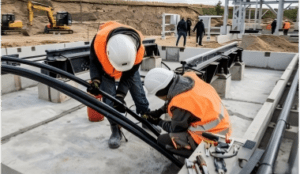
IEEE 1185-2019 explicitly states that installation damage is the single greatest cause of wire and cable failures. The standard‘s purpose is “to provide guidance to help prevent installation damage, which is the single greatest cause of wire and cable failures.”
The DNV GL survey found that 52% of cable body failures originated from manufacturing defects and installation errors, 17% from third-party damage, and only 9% from cable ageing.
| Failure Mode | Key Causes | High-Risk Location | Diagnostic Methods | Prevention |
| Terminal loosening / overheating | Improper torque, wrong conductor class, oxidation/corrosion | Terminals, panel wiring, connectors | Infrared thermography, voltage drop measurement, visual inspection | Calibrated torque tools, Class 5 fine-stranded conductor, ferrules |
| Overload / overheating | Heat proportional to current squared, distributed generation, undersized cable | Cable body, especially in conduits and trays | Temperature sensors, insulation resistance testing, EVR method | Ampacity margin, derating factors, insulation temperature rating |
| Mechanical damage | Excessive bending, excessive pulling force, sharp edges, backfill stones | Installation path, direct burial, pull points | Sheath integrity test, TDR, visual inspection | Rollers, pulling force control, protective sleeves, sand bedding |
Q1: Why do low voltage cables fail at terminals?
NRC analysis of 1,035 low voltage cable failures shows that hookup and panel wire failures account for 36.4% — the single largest category. The most common cause is improper torque. NEC 2017 Section 110.14(D) now requires calibrated torque tools. Another common cause is the use of Class 1 solid conductors, which work-harden and fracture at terminals after repeated bending.
Q2: How do I know if my panel wiring needs Class 5 conductor?
If the conductor needs to be bent multiple times inside the cabinet, or if it may be touched or moved by maintenance personnel after installation, use Class 5 fine-stranded conductor. Class 1/2 conductors work-harden during repeated bending — the copper becomes brittle and eventually fractures at the terminal. This type of break is invisible during visual inspection.
Q3: Can solar panels overload my existing cables?
Possibly. A 2026 study notes that distributed generation can cause high load variation and reverse power flow, while low voltage cable networks were not designed for these new stresses. Total load and generation may exceed cable rated capacity, causing short-term temperature rise and shortening expected cable life.
Q4: What is the biggest cause of cable installation damage?
IEEE 1185-2019 explicitly states that installation damage is the single greatest cause of wire and cable failures. DNV GL survey shows 52% of cable body failures originate from manufacturing defects and installation errors. Common damage includes excessive bending, excessive pulling force, sharp edge abrasion, and backfill damage.
Q5: How do I check if a terminal is loose?
The most direct method is infrared thermography to detect abnormal terminal temperature rise. You can also measure voltage drop across terminals under load. If voltage drop exceeds standard limits, it indicates poor contact. NRC data shows that the most significant failure cause for connectors is oxidation/corrosion/dirt (44%), followed by high resistance/open circuit (48%).
Contact us for product specifications, test reports, and application support.
Tel: +86-371-60547601
WhatsApp: +8613598056591
Email: [email protected]