IEC 60228 is the international standard for cable conductors. It classifies conductors into Class 1, Class 2, Class 5, and Class 6. This is not a quality ranking — it is a structural classification. Each class corresponds to a different level of mechanical flexibility and a different set of application scenarios.
For procurement professionals selecting low-voltage cables, conductor class directly affects installation method, service life, and termination reliability. This article provides an objective overview of each conductor class — structure, performance, and application positioning.
IEC 60228 specifies the classification, dimensions, and resistance requirements for cable conductors, covering copper, aluminium, and aluminium alloy conductors from 0.5 mm² to 3500 mm². The core logic of conductor classification is simple: the conductor structure is specified according to the expected operating environment of the cable.
| Class | Name | Typical Application |
| Class 1 | Solid conductor | Fixed installation |
| Class 2 | Stranded conductor | Fixed installation or occasional movement |
| Class 5 | Fine-stranded conductor | Frequent bending |
| Class 6 | Extra-fine stranded conductor | Extreme dynamic applications |
Key note: Class 3 and Class 4 are not defined in IEC 60228. The standard classifies conductors by flexibility level, not by usage scenario or cable type.
For procurement: Conductor class is not a “grade.” It is a structural category. Selection should match the actual operating conditions of the project, not a preference for a particular class.
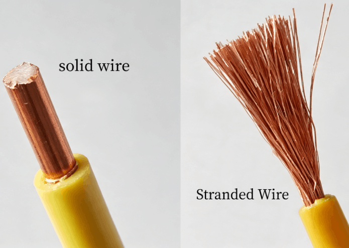
Structure: A single metal wire. The nominal cross-section is determined by the maximum DC resistance at 20°C.
Examples: 1.0 mm² = 1 × 1.13 mm; 2.5 mm² = 1 × 1.78 mm; 6.0 mm² = 1 × 2.76 mm.
Typical applications: Building wiring, fixed connections inside switchgear, concealed wiring in residential buildings.
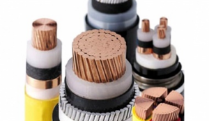
Structure: Multiple metal wires stranded together, with relatively thick individual strands. The nominal cross-section is determined by both the minimum number of wires and the maximum DC resistance at 20°C.
Examples: 1.0 mm² = 7 × 0.43 mm; 2.5 mm² = 7 × 0.67 mm; 6.0 mm² = 7 × 1.04 mm; 10 mm² = 7 × 1.35 mm.
Typical applications: Large cross-section cables in fixed installations, industrial power distribution, grid wiring.
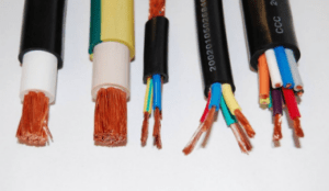
Structure: A large number of fine metal wires stranded together. The nominal cross-section is determined by the maximum individual wire diameter and the maximum DC resistance at 20°C. Note: Class 5 has a higher DC resistance than Class 2 at the same nominal cross-section.
Examples: 1.0 mm² ≈ 30 × 0.21 mm; 2.5 mm² ≈ 46–50 × 0.26 mm; 6.0 mm² ≈ 78–84 × 0.31 mm; 10 mm² ≈ 77–80 × 0.41 mm; 25 mm² ≈ 190–200 × 0.41 mm.
Typical applications: Control cabinet wiring, mobile equipment, cable carriers, extension cords.
Structure: Even more, finer wires stranded together. Individual wire diameter is smaller than Class 5.
Examples: 1.0 mm² ≈ 56 × 0.16 mm; 2.5 mm² ≈ 140 × 0.16 mm; 6.0 mm² ≈ 186–192 × 0.21 mm; 10 mm² ≈ 320 × 0.21 mm; 25 mm² ≈ 760 × 0.21 mm.
Typical applications: Robot cables, reeling cables, automation systems, high-frequency bending applications.
| Class | Structure | Individual Wire Diameter | Example (1.0 mm²) | Flexibility |
| Class 1 | Solid | — | 1 × 1.13 mm | Low |
| Class 2 | Stranded | Relatively thick | 7 × 0.43 mm | Medium |
| Class 5 | Fine-stranded | 0.21–0.51 mm | 30 × 0.21 mm | High |
| Class 6 | Extra-fine stranded | 0.16–0.21 mm | 56 × 0.16 mm | Very high |
Typical data (bare copper, 20°C, Ω/km):
| Nominal Cross-Section | Class 1 | Class 2 | Class 5 | Class 6 |
| 1.0 mm² | 18.1 | 18.1 | 19.5 | 19.5 |
| 2.5 mm² | 7.41 | 7.41 | 7.98 | 7.98 |
| 6.0 mm² | 3.08 | 3.08 | 3.30 | 3.30 |
| 10 mm² | 1.83 | 1.83 | 1.91 | 1.91 |
| 25 mm² | 0.727 | 0.727 | 0.780 | 0.780 |
Source: IEC 60228 resistance tables.
Interpretation: Class 5/6 DC resistance is approximately 5%–8% higher than Class 1/2. This is due to the small gaps between individual wires in a stranded construction, which increase the effective length, and the larger surface area of finer wires.
At power frequency (50/60 Hz), the skin effect has very limited impact on low-voltage cables. The 60 Hz AC resistance of a solid conductor is only about 0.3%–0.7% higher than its DC resistance.
Ordinary stranded conductors do not effectively reduce the skin effect — the individual wires are not insulated from each other, so high-frequency current still concentrates near the overall conductor surface. Only Litz wire (individually insulated strands) can significantly reduce skin effect losses at frequencies above 1.5 MHz.
| Performance | Class 1 | Class 2 | Class 5 | Class 6 |
| Flexibility | Low | Medium | High | Very high |
| Bending life | Very low | Low | High (10,000+ cycles) | Very high (1,000,000+ cycles) |
| Vibration fatigue resistance | Poor | Moderate | Good | Excellent |
| Termination method | Screw terminals | Screw / crimp | Ferrules recommended | Dedicated terminals |
Class 2 stranded conductors (19–61 wires) can withstand moderate bending without work hardening. Class 5 fine-stranded conductors significantly reduce conductor fatigue beyond 10,000 bending cycles. Class 6 extra-fine stranded conductors can support over 1,000,000 bending operations.
| Application | Recommended Class | Technical Basis |
| Building conduit wiring | Class 1 or 2 | Fixed installation, no movement |
| Switchgear internal wiring | Class 2 | Fixed installation, easy termination |
| Control cabinet wiring | Class 5 | Limited space, some flexibility needed |
| Mobile equipment power supply | Class 5 | Frequent bending, fatigue resistance |
| Cable carriers | Class 5 or 6 | Continuous reciprocating bending |
| Robot cables | Class 6 | High-frequency bending + torsion |
| Reeling cables | Class 5 or 6 | Repeated winding + tension |
Three-step selection:
1.Will the cable move after installation? No → Class 1/2; Occasionally → Class 2/5; Frequently → Class 5/6.
2.Is the installation space complex? Straight runs → Class 1/2; Bends required → Class 5/6.
3.What is the termination method? Screw terminals → Class 1/2; Ferrules → Class 5/6.
Q1: IEC 60228 class 1 vs class 2 — what‘s the difference?
Class 1 is a solid conductor made of a single metal wire. Class 2 is a stranded conductor made of multiple wires. Both have the same DC resistance limits, but Class 2 is more flexible. Class 1 is used for fixed wiring that does not need to bend. Class 2 is used for fixed installations that require some bending, especially large cross-section cables.
Q2: Class 5 or Class 6 cable — which one do I need?
Both are fine-stranded conductors. The difference is individual wire diameter and bending life. Class 5 has individual wire diameters of 0.21–0.51 mm and is used for control cabinet wiring, mobile equipment, and cable carriers. Class 6 has individual wire diameters of 0.16–0.21 mm and is used for robots, reeling cables, and high-frequency bending applications. The choice depends on bending frequency and bending radius — not on “finer is better.”
Q3: Solid or stranded conductor for control cable?
It depends on whether the cable will move after installation. Fully fixed, no vibration → solid conductor (Class 1) offers lower cost and more reliable termination. Vibration, bending, or occasional movement → stranded conductor (Class 2 or 5). For fixed cabinet wiring with limited space, Class 5 fine-stranded is often chosen for easier bending and termination.
Q4: What conductor class for vibrating equipment?
Class 5 or Class 6 fine-stranded conductors are recommended for vibrating environments. Solid conductors are prone to fatigue fracture at terminals due to stress concentration. Stranded conductors distribute stress and offer better vibration fatigue resistance. Ferrules are also recommended to reduce the risk of terminal loosening.
Q5: Wrong conductor class — what happens?
Using Class 1/2 in applications requiring frequent bending can lead to conductor fatigue fracture within a short period, causing signal interruption or equipment downtime. Using Class 5/6 in fully fixed applications does not cause failure, but increases procurement cost, and fine-stranded conductors are more prone to loosening under screw terminals — ferrules are required. The consequence depends on the application, not an absolute rule.
Q6: How to verify conductor class on cable datasheet?
Check two parameters: the number of individual wires × individual wire diameter, and the maximum DC resistance at 20°C. These are the core criteria for determining conductor class under IEC 60228. If a supplier only states “compliant with IEC 60228” without providing specific construction data, the class cannot be verified. Third-party sampling inspection of conductor resistance and dimensions can be arranged after delivery.
Tel: +86-371-60547601
WhatsApp: +8613598056591
Email: [email protected]