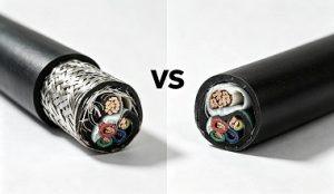
Control cable failures do not cause immediate power loss like power cables. They are more insidious: signal drift, equipment misoperation, system instability. The root causes typically concentrate in three areas — conductor, insulation, and sheath. Understanding the full chain of these three failure modes — from symptoms to solutions — is fundamental to procurement selection and acceptance inspection.
Control cable failures concentrate in three areas: conductor, insulation, and sheath. These three failure modes are not isolated — sheath damage allows moisture ingress, which leads to insulation failure; insulation failure causes short circuits, and the resulting overcurrent can overheat and break the conductor.
| Failure Mode | Typical Symptoms | High-Risk Scenarios | Direct Consequences |
| Conductor Breakage | Intermittent signal loss, abnormal resistance | Cable carriers, moving equipment, vibration | Signal loss, system downtime |
| Insulation Failure | Insulation resistance drop, short circuit | High temperature, overload, joint areas | Breakdown, fire risk |
| Sheath Damage | Cracking, abrasion, swelling | Outdoor, oil exposure, dragging, low temperature | Moisture ingress, insulation degradation |
Intermittent signal loss, abnormally high conductor resistance, complete open circuit. Failures typically occur at fixed bending points, terminal connections, or vibration zones.
Conductor structure mismatch. Class 1 or Class 2 conductors intended for fixed installation are used in applications requiring frequent bending. Solid or coarse-stranded conductors concentrate stress during repeated bending, and individual wire breakage gradually propagates. According to IEC 60228, Class 5 or Class 6 fine-stranded conductors should be specified for dynamic applications.
Conductor material defects. High oxygen content, excessive impurities, or improper annealing increase conductor brittleness. ASTM B3 specifies clear requirements for copper conductor resistivity and mechanical properties.
Improper terminal crimping. Wrong crimping tool, excessive or insufficient crimping force damages or loosens the conductor at the terminal. UL 486A specifies performance requirements for crimped terminals.
Excessive pulling force during installation. Exceeding the conductor‘s allowable tensile stress during installation causes internal damage that only becomes apparent months after commissioning.
Decreased insulation resistance, partial discharge, short-circuit breakdown. Failures typically occur at cable ends, near joints, or in sections under long-term overload.
Operation above temperature limits. PVC insulation (70°C) accelerates aging when approaching its temperature limit. Molecular chain scission degrades insulation performance. XLPE/EPR insulation has a continuous operating temperature of 90°C (IEC 60502-1 Table 2), providing greater thermal margin.
Mechanical damage. Scratches, compression, or excessive bending during installation create defects inside the insulation. Under operating voltage, localized electric field concentration gradually develops into breakdown. IEC 60502-2 specifies minimum bending radius requirements.
Partial discharge. Voids, contaminants, or semiconductive layer protrusions inside the insulation distort the local electric field. PD continuously erodes the insulation until it penetrates. IEC 60270 specifies PD measurement methods.
Chemical attack. Oil, solvents, or corrosive gases penetrate the insulation, causing swelling, cracking, or conductivity.
Sheath cracking, abrasion penetration, swelling deformation. Damage itself does not directly cause electrical failure, but moisture, chemicals, and mechanical damage ingress through the breach, leading to insulation failure.
Material selection error. PVC sheath used in outdoor UV exposure or oily environments powders and cracks within months. Rubber sheath used in direct burial or high-abrasion scenarios lacks cut resistance. IEC 60227 and IEC 60245 specify material performance requirements for PVC and rubber cables respectively.
Mechanical abrasion. In cable carrier, reeling, or ground-dragging applications, the sheath continuously rubs against guides, rocks, or equipment edges, gradually thinning until penetration.
Chemical attack. Sheath exposure to engine oil, hydraulic fluid, acids, alkalis, or solvents causes swelling, softening, or cracking. ISO 1817 specifies rubber resistance to liquids test methods.
Low-temperature embrittlement. PVC becomes brittle below -15°C; minor impact during installation or operation can crack the sheath. Rubber sheath remains flexible at -40°C. IEC 60811-1-4 specifies low-temperature test methods.
Chemical swelling: Replace with chemical-resistant sheath material
| Failure Prevention Need | Selection / Acceptance Criteria | CN Cable Group Product |
| Prevent conductor breakage in dynamic applications | Specify Class 5/6 fine-stranded conductor, confirm strand count | SY Control Flexible Cable |
| Prevent signal distortion from EMI | Confirm shield type and coverage | CVV-S / LiYCY |
| Prevent insulation aging in high-temperature environments | Confirm temperature rating (XLPE/EPR 90°C) | N2XH LSZH Cable |
| Prevent sheath damage from oil/outdoor exposure | Confirm oil/UV resistance rating | H07RN-F Rubber Cable |
| Bulk delivery acceptance | Arrange third-party sampling inspection | Complete factory test reports available |
For project-specific control cable selection support, contact us.
Tel: +86-371-60547601
WhatsApp : +8613598056591
Email: [email protected]